Titan DX
Finale -- September 21, 2007 (additional comments 5/24/2008). The Titan DX was removed from service today. It will be replaced by my extra HF9V. The primary HF9V will be replaced by a BigIR with 80 meter coil but that is another story. During the time in which it was the primary station antenna (13 months) I worked 157 DXCC countries including more than 100 on CW. It worked a total of 49 states.
Mechanical problems began within a month of installation. The constant use of sheet metal screws instead of proper nuts, bolts, and lockwashers or clamps, coupled with the inflexible connecting wires and stress on crimped wires, was evident even then. The narrative below is in roughly reverse chronological order and shows my starting with great enthusiasm and gradually getting more disappointed as time went by. I have since lost my fear of radials and the primary antenna is a BigIR Mk III with 80/60 meter coil and 30 50-foot radials. It is a killer antenna.
Examination of the Titan after removal confirms which has been previously said below -- it cannot stand up over time unless securely guyed. Even then I have my doubts. More than half of the wires to the tuning bars have broken. Half a dozen sheet metal screws are missing. These should have all been heavy-duty stainless screws all of the way through the element instead of simply threading them into one side or slotted pipe and clamps should have been used. Some of this damage is no doubt due to the winds. But the sagging counterpoise which now touches the ground all of the way around the antenna is simply due to poor design. The counterpoise should have been guyed to the main mast thus removing the downward forces that eventually bent the aluminum.
While I have used the antenna until recently with my second radio during contest operations it simply never performed well on 80 meters. The HF9V with only 16 15 foot radials easily outperforms it on 80 and 75 and has the advantage that you can easily retune it for various segments of the band for contests. Retuning the Gap is ridiculous -- requiring taking the antenna down and replacing a tuning capacitor at the very top of the antenna. In fact, my tests show the HF9V equal to or better than the Gap on all bands except for 17 meters where the Gap seems particularly effective and the HF9V only adequate.
Summary: This antenna is not mechanically strong. It should be guyed if it is ever subject to more than minimal wind gusts. The counterpoise should be guyed from above to the mast to prevent sag and deterioration of the supports.
Update (2002): The antenna was installed 20 February 1999 and has been aloft for nearly four years. It was taken down for re-aligning and repairing some wiring after a year. So how is it doing after four years? Not so well. More...
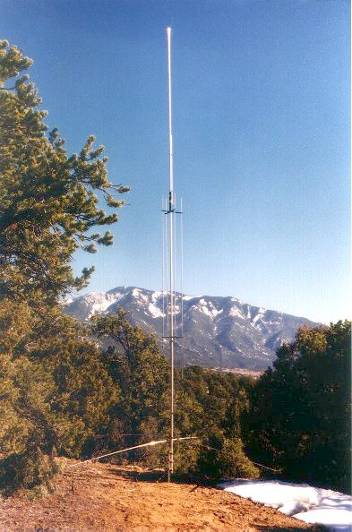
After a couple of years aloft (2001), a picture of the results of the mechanical aspects of this antenna after exposure to wind. Click here for pictures and text.
Gap Titan diagram and tuning information. I found this on the net. It appears to be correct although the 30 meter tuning isn't really explained. Shouldn't matter as the 30 meter tuning was not a big problem.
General Commentary (1999). After two years of operation at our second home above Valdez, New Mexico using a makeshift 20 and 10 meter dipole mounted approximately 4 feet off of the roof, I began exploring options for a more permanent antenna installation. The dipole was far too close to the operating position, creating RF problems in the shack. It was also close to the garage and operation on certain frequencies caused the doors to open and close. Worse, the shack includes 3 Pentium servers of various types, a 100Mhz switched data network, and a 56kbs dedicated internet link. The resultant RF noise was severely limiting operation.
The location is on sloping ground covered with piñon trees averaging 10-15 feet high. Aesthetics ruled out tower, beams, and extensive wire antennas so a vertical seemed like a good compromise. However, the ground is dry and rocky adobe and didn't seem particularly attractive to implementation of extensive radial systems.
After a lot of research, I purchased a Gap Titan DX from the Amateur Electronic Supply store in Las Vegas.
The antenna is advertised as covering all bands 40 through 10 (including WARC) with SWR of 2:1 or less, and 100 KHz. of 80 meters at 2:1 or less. A small capacitor at the top of the antenna determines what portion of the 80 meter band is tuned.
AES was incapable of telling me what 80 meter segment the antenna was delivered with, so I called Gap. They were quite helpful and indicated that all AES antennas were configured with the 3900 kHz. capacitor. I asked Gap to ship me a 3600 kHz. capacitor, figuring I would get a credit from AES for the difference.
The antenna was shipped via UPS second-day air. It is just barely under the limits. UPS (of course) didn't bother delivering it in two days and the antenna finally arrived at 3pm, Friday February 20 only two hours before the start of the ARRL CW DX contest -- and maybe 2 1/2 hours before dark.
The antenna is a complex combination of tuning bars, wires, coax, and a center
insulator (the "gap"). I would estimate that careful
 assembly
would take 4 or 5 hours. Nonetheless, it was assembled by about 5:20pm and then the
real fun began. By then the temperature was in the high 20's with a 10-15 mph wind.
Not the ideal conditions for positioning a 25-foot, dozen pound vertical onto a
supporting pipe. But I was finished by about 5:45pm. The antenna was
immediately checked on all bands and seemed to function fine. SWR on 40 CW was 2.5:1
and on 15 CW was 2.7:1, but it was dark and supposedly this was a "no-tune"
antenna (more on that later) so I simply let the AT-180 tuner attached to the IC706 do its
job and off I went.
assembly
would take 4 or 5 hours. Nonetheless, it was assembled by about 5:20pm and then the
real fun began. By then the temperature was in the high 20's with a 10-15 mph wind.
Not the ideal conditions for positioning a 25-foot, dozen pound vertical onto a
supporting pipe. But I was finished by about 5:45pm. The antenna was
immediately checked on all bands and seemed to function fine. SWR on 40 CW was 2.5:1
and on 15 CW was 2.7:1, but it was dark and supposedly this was a "no-tune"
antenna (more on that later) so I simply let the AT-180 tuner attached to the IC706 do its
job and off I went.
The DX test went well enough with limited hours of operation. Antenna was used on 80 through 10. About sixty countries were worked including all continents but Africa. Immediately after the test, we returned to the primary QTH in St. Louis.
I arrived back in Valdez in early March for a week's visit. The antenna was behaving poorly -- in fact loading it up managed to fry the AT-180. I wrote this off to a lot of wet snow on the RG-213/U coax, but later examination revealed that a screw had popped loose above the "gap" -- thus disconnecting two of the tuning bars. Since heavy snow was expected that evening, down came the antenna (in winds, yet again) and the screw was replaced and tightened as much as possible.
This restored full operation and in the following week, all continents were worked on numerous bands -- particularly 12 meters -- including Norfolk Island, San Andres, the Marshall Islands, Gambia, Zambia, and West Kiribati.
On return to Valdez in May, 1999 it was discovered that not only had the same screw departed again but prior to its departure one of the spade lugs had broken and all of the various standoff insulators had also slipped. Once again, down came the antenna for repairs -- which took about a half hour. The broken wires were replaced with flexible Copperweld -- as were several other wires -- and the insulators repositioned and tightened as much as possible.
I have now adjusted the 40, 15, and 12 meter frequency coverage and the antenna meets all specifications. It does well, but I would recommend guying if it is to be erected in a windy environment such as this. We have frequent gusts in the 40 mph range, year round.
Except on 80, I manage to work most of what I hear and get through the pileups quite regularly. I've worked 149 countries during our occasional visits including Taiwan on RTTY. I worked T31K on 20 SSB the first night of their operation there! During the 1999 CW SS, I recorded 666 QSO's with a clean sweep of 79 sections in only 18 hours of operation. This won me the Rocky Mountain Division Unlimited Class plaque!
In the fall of 1999, I upgraded the station to include an Icom PW-1 KW amplifier. The antenna seems to handle this well, although Gap has suggested that I limit 80 meter power to 500 watts on RTTY. Their concern is with damaging the 80 meter matching section within the antenna, which is constructed of small diameter coax.
Construction
The antenna is constructed of aluminum tubing throughout. Phasing and internal feeding is done with RG8X-like coax. A PL-259 UHF connector is supplied to connect the antenna. This was a bit of a surprise, but fortunately I had a double female connector on hand. The tuner rods are also aluminum and connected to the primary elements using medium-gauge stranded wire with crimped connectors on the ends. The rods are separated from the main elements using primitive standoff insulators fashioned from plastic and held on the mast using large hose clamps through holes in the tubular plastic. Properly aligning these standoffs is one of the more tedious tasks in the construction and would be facilitated by placing the antenna on a couple of sawhorses. The rods are positioned between the standoffs using gravity and limit screws. Since they bear no load they theoretically move independently of the main elements when it bends in the wind. In my case, I had failed to tighten the standoffs sufficiently and they changed position, breaking some of the interconnecting wiring. My solution was slightly longer and more flexible wire interconnects as well as tightening the hose clamps as much as possible. Gap probably shouldn't be blamed for this particular problem -- the antenna was assembled very quickly.
The antenna is insulated from the mounting mast by plastic rings. Because of this, the outside dimension of the mounting mast is fairly critical.
The antenna includes a large (80" on a side) square counterpoise approximately 16 inches above the bottom of the antenna mount. The manual indicates that this counterpoise must be avoided during transmission. It also indicates that total length of the wire strung around the counterpoise effects the 40-meter resonant frequency. In practice, interaction in the vicinity of the counterpoise is great enough that any antenna measurements must be made many feet away.
The instruction manual is primitive and not professionally printed. Drawings are by hand and sparse. It is adequate, but there is virtually no information on the theory of operation or which of the tuner bars effect which frequency setting. While the antenna is advertised as no-tune, two of the tuner bars are variable length, and the counterpoise is set for 40 meters. It is probably safe to say that it is no-tune if one is primarily interested in the phone segments of the bands.
After Sales Support/Tuning
After sales assistance is by telephone and email. Email is answered in a couple of days and is generally helpful. In my case, 40 and 15 meters were not correctly tuned and 12 meters was marginal. An email indicated that the counterpoise should be adjusted for 40 and the 23 inch tuner extension adjusted for 15. The counterpoise segment for 40 meter was radically shortened, producing good 40 meter SWR and bandwidth.
Adjustment of the 23 inch tuner bar produced proper 15-meter response.
Feeling bold with these successes I guessed that the other adjustable bar, being the next shorter from the 23 inch tuner, would be the 12-meter adjustment. It was, although 12-meter response is never better than 1.5:1 even at best settings. The antenna performs well on 12 meters, however.
A note from KE6BSF indicates that ten meter coverage can be adjusted by varying the length of the short segment of the counterpoise. This is the one that terminates that end of the black rope is tied to. Rod also suggested sliding the 30 meter rod (the longest of the rods) up and down in the mounts to vary the resonance there. Wire ties are then used to lock it in place. This bothers me a bit since the entire antenna is tuned by these loosely confined rods -- wonder how much the SWR is varying in the high winds we have here on the mountain?
Note that the tuning adjustments are not documented in the "manual" and are only available by querying the factory case-by-case or by examining this diagram.
I did spend some time tuning with the MFJ 259B antenna analyzer. This really helps although there are so many resonant points with this antenna that it can be confusing to tune. I spent a bit of time trying to get the 40m resonance down below 8 mhz only to discover that there was a 6.6 mhz resonance that tuned into 40m nicely -- the counterpoise had just started out too long.
Conclusion (as of 4/15/2002)
I'd recommend the antenna to anyone wanting a no-radial solution and who doesn't mind messing with a kit antenna. Performance seems as good or better as any small vertical. The only real problem is 80 meters. I've used the HyGain DX-88 and the Butternut HF9V on 80 in St. Louis with just sixteen 15 foot radials and they're better on virtually all bands -- except 17 meters in the case of the HF9V. While this isn't an A-B test, the definite impression is that the Titan is a poor performer on 80. I just don't work much of what I hear.
The only other real problem with the antenna is that in most locations it will be difficult to separate the counterpoise from random foot traffic as required by the FCC RF radiation regulations. I'd suggest mounting it about 6-8 feet above the ground but this would almost certainly require guying -- this is a big antenna and really moves in the wind.
The antenna is no longer my primary antenna in NM. A Butternut HF9V which performs better on 80m and 10m and doesn't have the 80m power limitation is now primary, but the Titan DX is still used for the second contest station and performs fine. No additional maintenance has been performed for more than a year although as noted at the beginning of this discussion, it is past due.
(4/15/2002)